Cyclic stretching rig
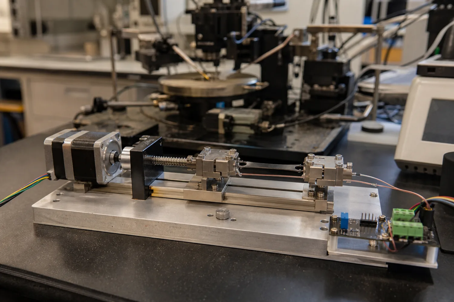
A bench rig that stretches a conductor strip a thousand times and logs its resistance.
- Process
- Printed and machined parts, the lab's electronics
- Quantity
- 1 rig
- Region
- US lab
- Environment
- Lab bench
- Image
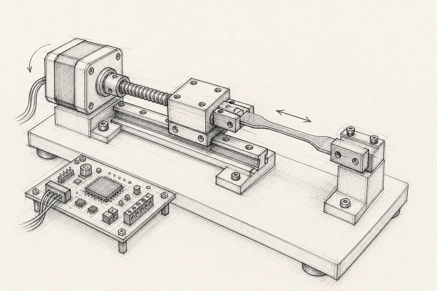
- Concept image, not to scale
Example brief · not client workWe wrote this brief ourselves; it is not client work. The 3D model, drawings and inspection results are in production and will replace the placeholders below.
The request, as a client would send it
We need to cycle our stretchable conductor samples and log resistance while they stretch. Samples are strips 10 mm wide with a 50 mm gauge length; we want to stretch them to 50 % strain (25 mm of travel) for 1,000 cycles or more at about 0.5 Hz. We already have a NEMA 17 stepper with a driver, an Arduino Uno and an ADS1115 16-bit ADC board, and we would like to use them. The clamps must hold the strip without cutting it and must not short it: the resistance is read through the clamps. The rig has to fit a 300 x 150 mm spot on the bench next to our probe station. We would like the parts, instructions and the code that runs the cycles and writes resistance against position to a CSV file on the laptop.
Attached by the client
Links in the request
- Arduino Uno Rev3 (opens in a new tab)controller the lab already has
- TI ADS1115 (opens in a new tab)16-bit ADC the lab already has
Product names are their owners' trademarks and are used only to describe size or parts.
Highlighted numbers came with the request; they are the values we would design to.
What we considered
| No. | Consideration | How it is checked |
|---|---|---|
| 01 | 25 mm of travel, straight A lead screw and a rail carry the moving clamp; the stepper sits at the fixed end. | Stage travel covers 25 mm plus margin inside the 300 x 150 mm footprint. |
| 02 | Clamps that grip and measure Insulated jaws with a contact strip on each side hold the sample flat and carry the resistance reading. | Jaw opening fits the strip; contacts insulated from the frame. |
| 03 | Built around the lab's parts Mounts for the NEMA 17, the Uno and the ADS1115 use their published hole patterns. | Hole patterns against the parts' drawings; connector access clear. |
| 04 | Code that logs The code runs a set number of cycles and prints position and resistance lines that the laptop saves as CSV. | Pin map matches the wiring diagram; the code builds for the Uno. |
The question we would ask you
Do you need a load cell to record force as well?
Force changes the moving clamp, adds an amplifier board and makes the rig longer; without it the rig records strain and resistance only.
What we do not claim
- Force or strain accuracy
- Fatigue results for the lab's material
- Electrical safety approval
CAD, drawings and inspection
Model, drawings, parts list and inspection report
The 3D model, dimensioned drawings, parts list, and the first-try and final inspection results will appear here after the first build. First-try failures stay visible.