Desktop label printer
A 4-inch thermal label printer for shipping desks: a top cover on a rear hinge, a sprung print head and a roll that drops in from above.
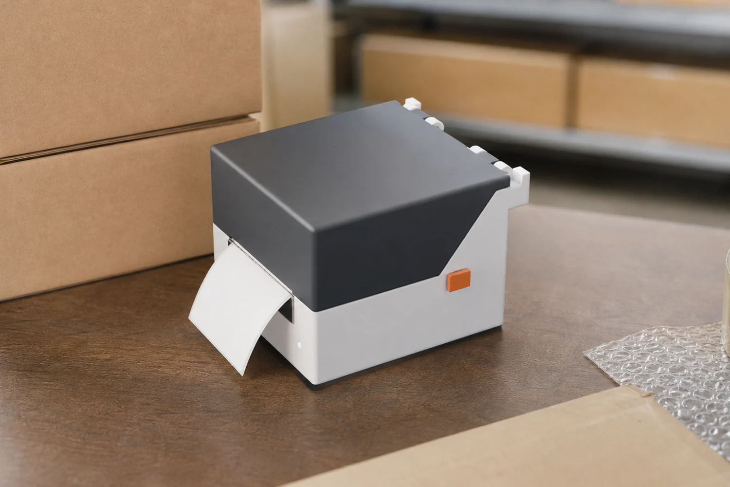
- Process
- Printed prototypes → Injection
- Quantity
- 20 → 3,000 a year
- Region
- US, EU
- Environment
- Shipping desk, indoor
- Image
- Concept image, not to scale
Example brief · not client workWe wrote this brief ourselves; it is not client work. The design below is a hand-built CAD sample drawn to the concept sketch: it is not our engine's output, and it has not been built or tested physically.
The request, as a client would send it
We make thermal label printers for shipping desks and small warehouses, and we are designing the housing of a new 4-inch desktop model. It prints 4 x 6 inch shipping labels from rolls up to 127 mm across on a 25.4 mm (1 inch) core. Inside: our main board, 120 x 80 mm, with USB-C and Ethernet on its back edge and a 24 V input from an external adapter. A 203 dpi thermal print head on a sprung bracket, a platen roller driven by a small stepper motor through two gears, and a label gap sensor under the paper path. The top cover opens on a rear hinge to about 100 degrees and stays there, so the roll drops in from above. A release button on the side lets it go, and it shuts with one hand. The print head must come down square on the roller every time the cover closes. A tear bar at the front, one button with an LED beside it, rubber feet. The whole printer must stay within 200 mm wide, 240 mm deep and 180 mm tall with the cover shut. First 20 printed for testing, then about 3,000 a year molded. We will sell it in the US and the EU and plan to certify to IEC 62368-1.
Attached by the client
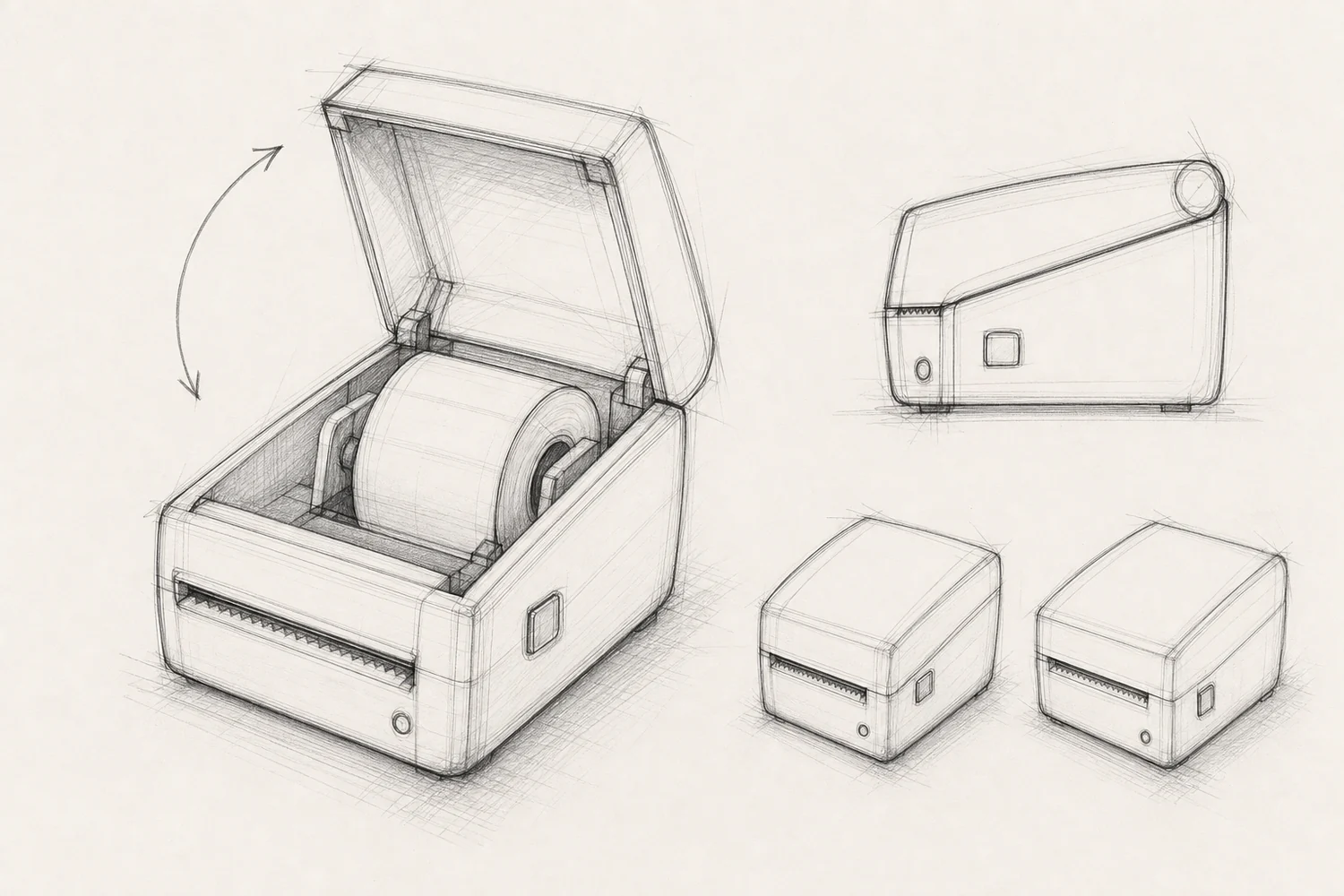
Links in the request
- Thermal printing (opens in a new tab)How a direct thermal print head marks the label
- IEC 60950 and IEC 62368-1 (opens in a new tab)IEC 62368-1 replaced IEC 60950 for IT equipment safety
Product names are their owners' trademarks and are used only to describe size or parts.
Highlighted numbers came with the request; they are the values we would design to.
What we considered
| No. | Consideration | How it is checked |
|---|---|---|
| 01 | The cover opens to 100° and stays A rear hinge with a stop holds the cover open while the roll goes in, and the open cover clears a wall behind the printer. | Cover swept through its opening against the base and the roll; stop angle and clearance behind listed. |
| 02 | The head lands square on the roller The print head rides on a sprung bracket inside the cover and comes down on the platen roller along its whole width when the cover shuts. | Head line over the roller axis with the cover shut; spring travel and contact points listed. |
| 03 | One button lets the cover go The side release button pulls two hooks off their catches, springs back, and the cover latches again when it closes. | Button travel against the hook engagement; the hooks clear when the button is pressed. |
| 04 | Molds, and keeps mains outside Even walls, ribs and draft for molding; the 24 V adapter keeps mains voltage out of the printer, designed toward IEC 62368-1. | Walls and draft against the molding rules; no mains wiring inside the housing. |
The question we would ask you
Roll inside only, or a rear slot for fan-fold labels as well?
A rear slot changes the back wall and adds a paper guide behind the roll cradle, and it needs a cover to keep dust out when it is not used.
What we do not claim
- IEC 62368-1 or any certification
- Print quality or speed
- Hinge and mechanism life in cycles
Sample CAD and the checks we ran
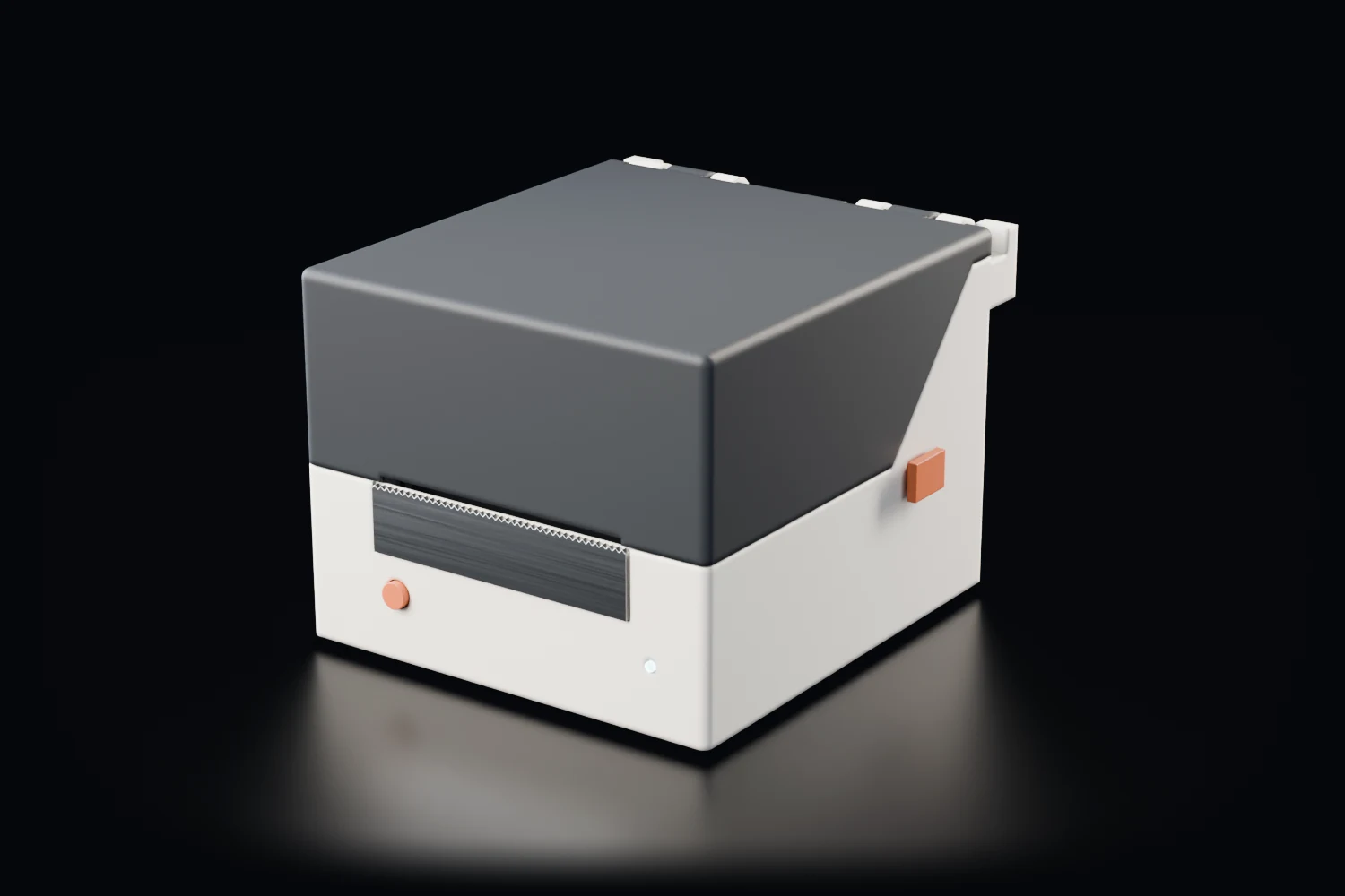
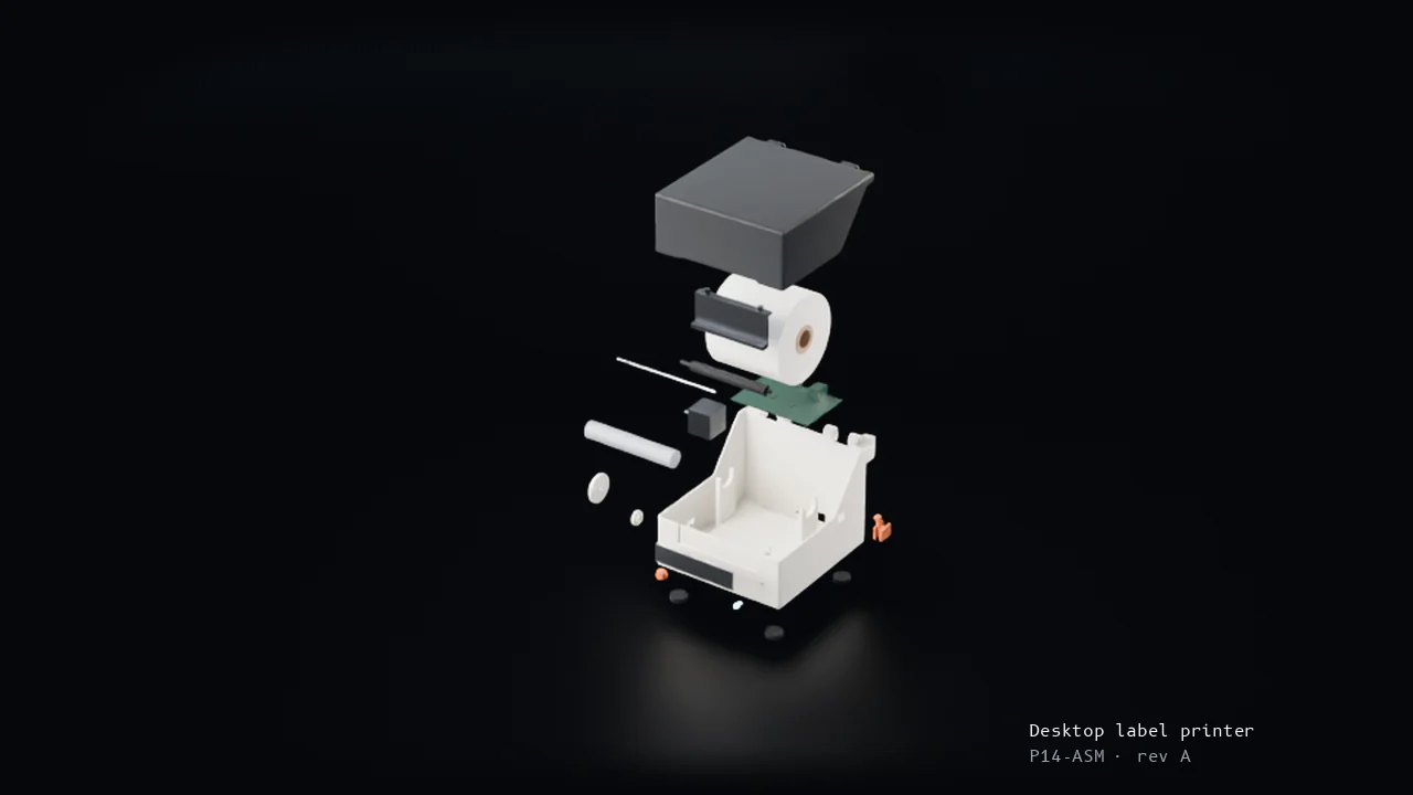
Sample designWritten by Anamor as a hand-built CAD sample for this page, drawn to the concept sketch. It is not our engine's output and it has not been built or tested physically.
P14-ASM
- 1Base housing
- 2Main circuit board
- 3Stepper motor
- 4Motor gear
- 5Platen roller
- 6Platen gear
- 7Tear bar
- 8Light pipe
- 9Feed button
- 10Release button
- 11Label roll
- 12Roll spindle
- 13Head bracket
- 14Top cover
- 15Hinge pin
- 16Rubber foot×4
Parts list · 19 parts
| No. | Part | Qty |
|---|---|---|
| 1 | Base housing | 1 |
| 2 | Main circuit board | 1 |
| 3 | Stepper motor | 1 |
| 4 | Motor gear | 1 |
| 5 | Platen roller | 1 |
| 6 | Platen gear | 1 |
| 7 | Tear bar | 1 |
| 8 | Light pipe | 1 |
| 9 | Feed button | 1 |
| 10 | Release button | 1 |
| 11 | Label roll | 1 |
| 12 | Roll spindle | 1 |
| 13 | Head bracket | 1 |
| 14 | Top cover | 1 |
| 15 | Hinge pin | 1 |
| 16 | Rubber foot | 4 |
What we measured on the sample
- Clearance at rest
- 0.50 mm smallest gapEvery pair of the 19 parts measured at rest (171 pairs); the value is the smallest gap found.
- Size against the request
- 197 × 224 × 156.5 mmRequest: 200 × 240 × 180 mm with the cover shut. Inside it.
- Release button
- 2.9 mmPushes in 2.9 mm before it meets the base, and 0.9 mm back out. Needs 2.5 mm: met.
- Top cover
- 99.7°Opens to 99.7° and rests on the base's stop pads; shut, it sits on the platen roller. Needs 95°: met.
Not done yet
- Dimensioned part drawings
- Process rule inspection (wall, draft, bend and hole rules)
- A physical build