Clip-on exposure badge
A matchbox-sized badge that logs noise and heat on a factory floor, sealed against dust and splashes.
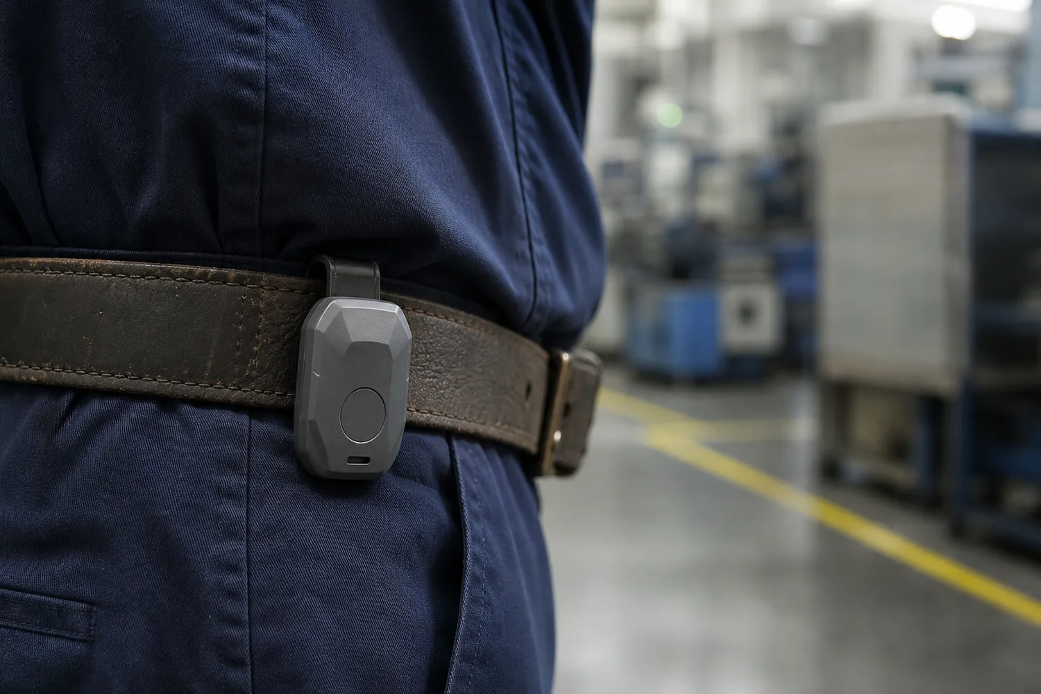
- Process
- Printed pilot → Injection
- Quantity
- 50 → 1,000
- Region
- US
- Environment
- Factory floor, worn
- Image
- Concept image, not to scale
Example brief · not client workWe wrote this brief ourselves; it is not client work. The 3D model, drawings and inspection results are in production and will replace the placeholders below.
The request, as a client would send it
We make a clip-on badge that factory workers wear on a belt or collar. It logs noise and temperature through the shift and sends the log to a supervisor's phone over Bluetooth at the end of the day. Inside: our PCB, 40 x 25 mm and 1.0 mm thick, with an nRF52832 module, a MEMS microphone on the top side and a temperature sensor at one edge. A 300 mAh LiPo pouch, 30 x 20 x 4 mm. One push button and one status LED. Charging through two magnetic pogo pins on the back. The case must stay within 52 x 34 x 14 mm and take a steel clip on the back. The microphone needs a sound port that dust and splashes cannot get through (we are aiming at IP54), and the temperature sensor must read the room, not the battery. First 50 printed for a pilot at one plant, then about 1,000 moulded.
Attached by the client
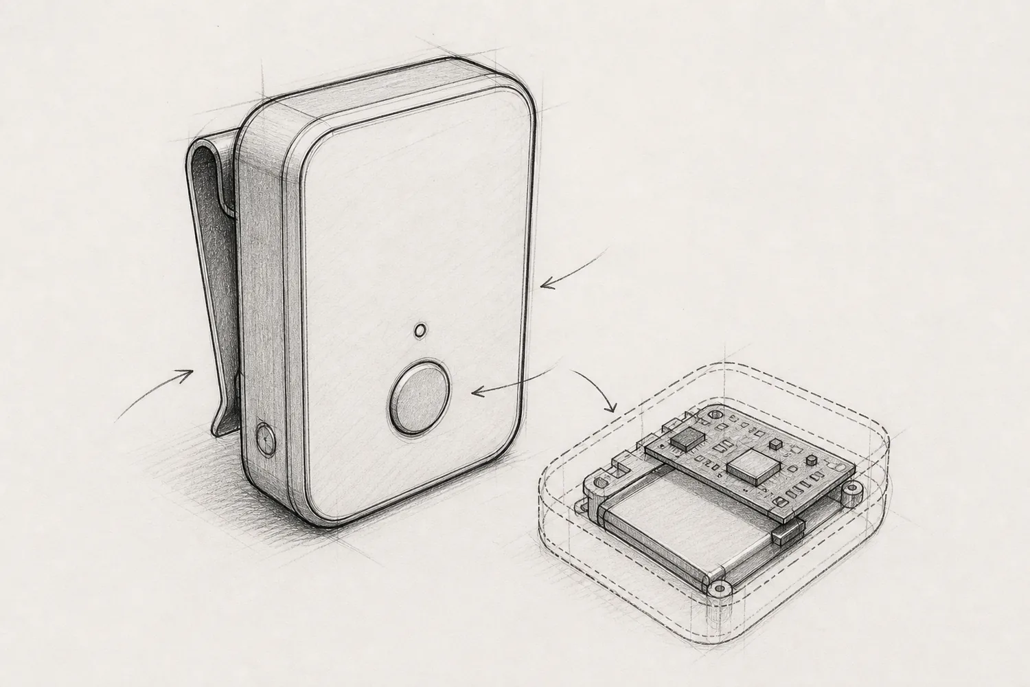
Links in the request
- Nordic nRF52832 (opens in a new tab)Bluetooth LE chip on the client's module
- IEC IP ratings (opens in a new tab)IP54: dust protected, splashing water
Product names are their owners' trademarks and are used only to describe size or parts.
Highlighted numbers came with the request; they are the values we would design to.
What we considered
| No. | Consideration | How it is checked |
|---|---|---|
| 01 | Everything fits within 14 mm Battery, board, button travel and the clip stack up inside the height limit with walls that mould. | Parts placed with clearance inside the 52 × 34 × 14 mm envelope; walls against the moulding rules. |
| 02 | The microphone hears through a sealed port A small sound port with a seat for a membrane keeps dust and splashes out and leaves the sound path open. | Port and membrane seat in line with the microphone; the IP54 rating itself is not claimed. |
| 03 | The temperature sensor reads the room The sensor sits at the board edge next to a vent, away from the battery and the radio. | Distances from the sensor to the battery and the module listed; vent beside the sensor. |
| 04 | Charging pins meet the dock The two pogo pins sit flush in the back with room for the clip beside them. | Pin positions against the clip footprint; clear zone around the pins. |
The question we would ask you
Belt clip, collar clip, or both?
A collar clip brings the badge closer to the ear and changes where the sound port should face; both means a clip that turns, which costs height.
What we do not claim
- IP54 or any rating
- Sound-level or temperature accuracy
- Battery life over a shift
CAD, drawings and inspection
Model, drawings, parts list and inspection report
The 3D model, dimensioned drawings, parts list, and the first-try and final inspection results will appear here after the first build. First-try failures stay visible.