1U CubeSat structure
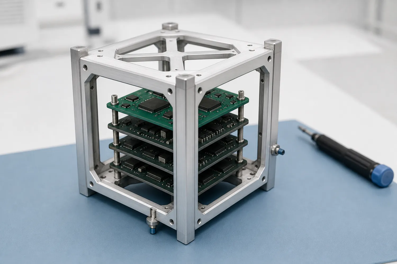
A student-built frame checked against the CubeSat Design Specification.
- Process
- CNC aluminium 6061-T6
- Quantity
- 2
- Region
- Global
- Environment
- University CubeSat
- Image
- Concept image, not to scale
Example brief · not client workWe wrote this brief ourselves; it is not client work. The design below was generated and checked by our engine as an internal test; read the notes under it before drawing conclusions.
The request, as a client would send it
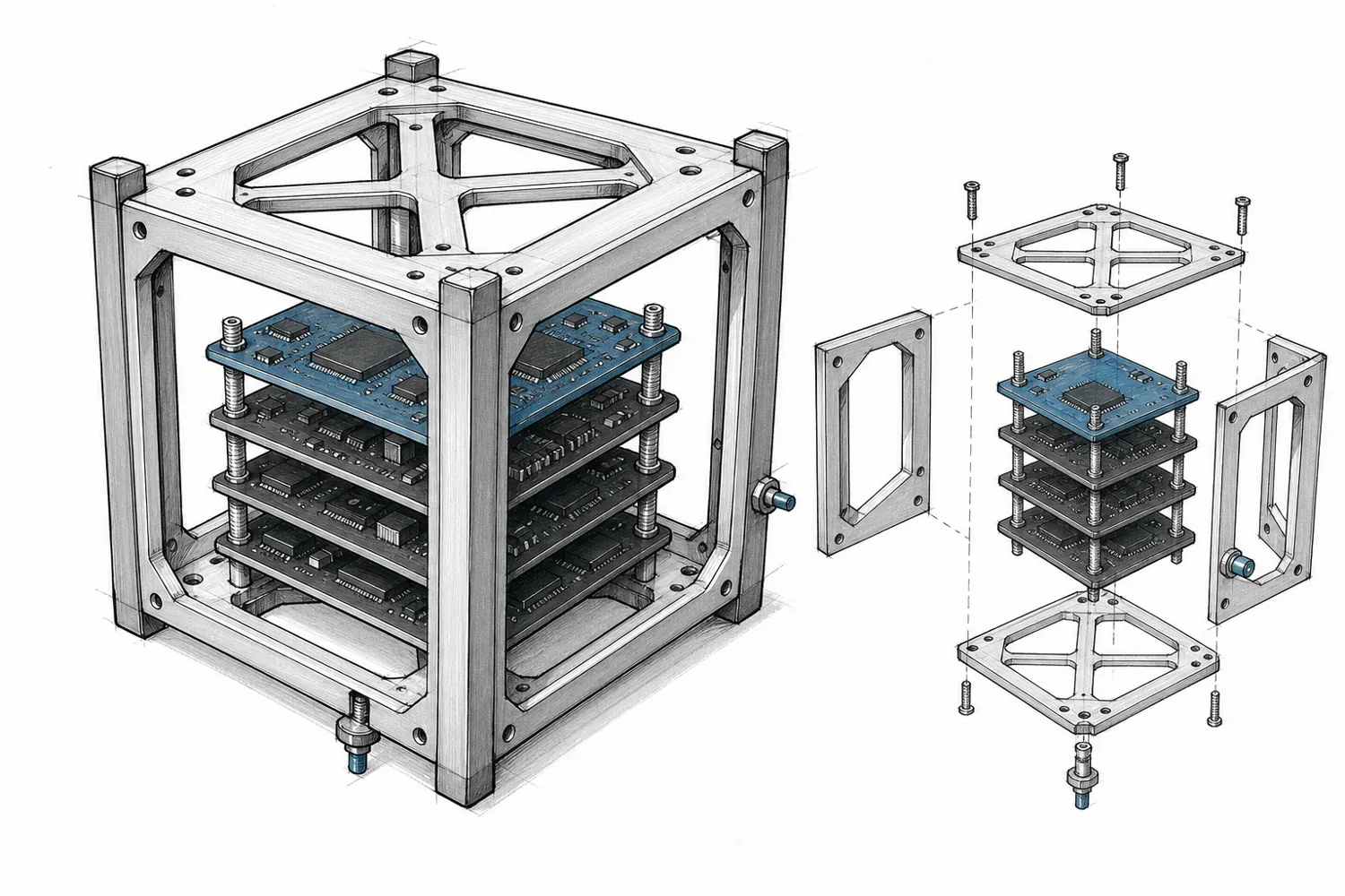
We're a university student team building our first 1U CubeSat for a launch opportunity in 2028. We'd like a primary structure we can machine at a local shop: two units, one flight-like for vibration testing and one for integration. It must follow the CubeSat Design Specification Rev 14.1: a 100.0 x 100.0 x 113.5 mm outer envelope, four corner rails at least 8.5 mm wide, nothing sticking out more than 6.5 mm from the rail surfaces, and a total mass under 2.00 kg. Inside: a PC/104-style stack of four 90 x 96 mm boards on four standoffs. One separation switch at a rail foot, and one remove-before-flight pin port on a side face. Solar panels will be mounted on the side faces later. Material: aluminium 6061-T6 with hard-anodized rails. For reference, there are commercial structures such as EnduroSat's 1U or KAIROSPACE's KSCS. We can't afford them, and we want to learn by making our own. Our first sketch is attached.
Attached by the client
Links in the request
- CubeSat Design Specification Rev 14.1 (Cal Poly) (opens in a new tab)1U drawing 100 x 100 x 113.5 mm; rails ≥ 8.5 mm; protrusion ≤ 6.5 mm
- EnduroSat 1U structure datasheet (opens in a new tab)98 g, Al 6061/6082
- KAIROSPACE KSCS structures (opens in a new tab)Al 7075, CDS 14.1
Product names are their owners' trademarks and are used only to describe size or parts.
Highlighted numbers came with the request; they are the values we would design to.
What we considered
| No. | Consideration | How it is checked |
|---|---|---|
| 01 | The CDS envelope, to a tenth Outer envelope 100.0 x 100.0 x 113.5 mm at ±0.1 mm, with the numbers cited from the CDS Rev 14.1 drawing. | Outer size and tolerance against the cited values. |
| 02 | Rails a deployer will accept Corner rails at least 8.5 mm wide with rounded rail ends. | Rail width and edge treatment measured on the model. |
| 03 | Nothing past the 6.5 mm line Every feature stays within 6.5 mm of the rail surfaces, leaving room for solar panels later. | Protrusion measured against the rail planes. |
| 04 | Switch and pin you can reach The separation switch at a rail foot and the remove-before-flight pin port can be reached with the structure assembled. | Clear access zones at both. |
The question we would ask you
Side frames machined as one piece with the rails, or bolted-on panels?
One piece is stiffer and lighter; bolted panels are easier to machine and let you reach the board stack.
What we do not claim
- Launch vibration or thermal-vacuum test results
- Flight qualification
From request to checked design
-
1 · Request
A student-built frame checked against the CubeSat Design Specification.
Plain-language brief with 3 links and a sketch. Only the text goes into the pipeline.
-
2 · Brief card
5 parts to make3 parts to fit11 pass criteria
Assumed
- Quantity 2 units as stated (one flight-like, one integration).
- Pocket floor / wall thickness 1.5 mm nominal, rails 8.5 mm wide; posting states no wall thickness.
- Board thickness 1.6 mm and 15 mm board pitch (PC/104 convention); posting gives only the 90 x 96 mm outline.
- and 3 more
Asked
- Which side face and Z height should the RBF port sit at relative to the stack connector?
- What is the first board's height above the bottom plate?
- and 1 more
-
3 · Design
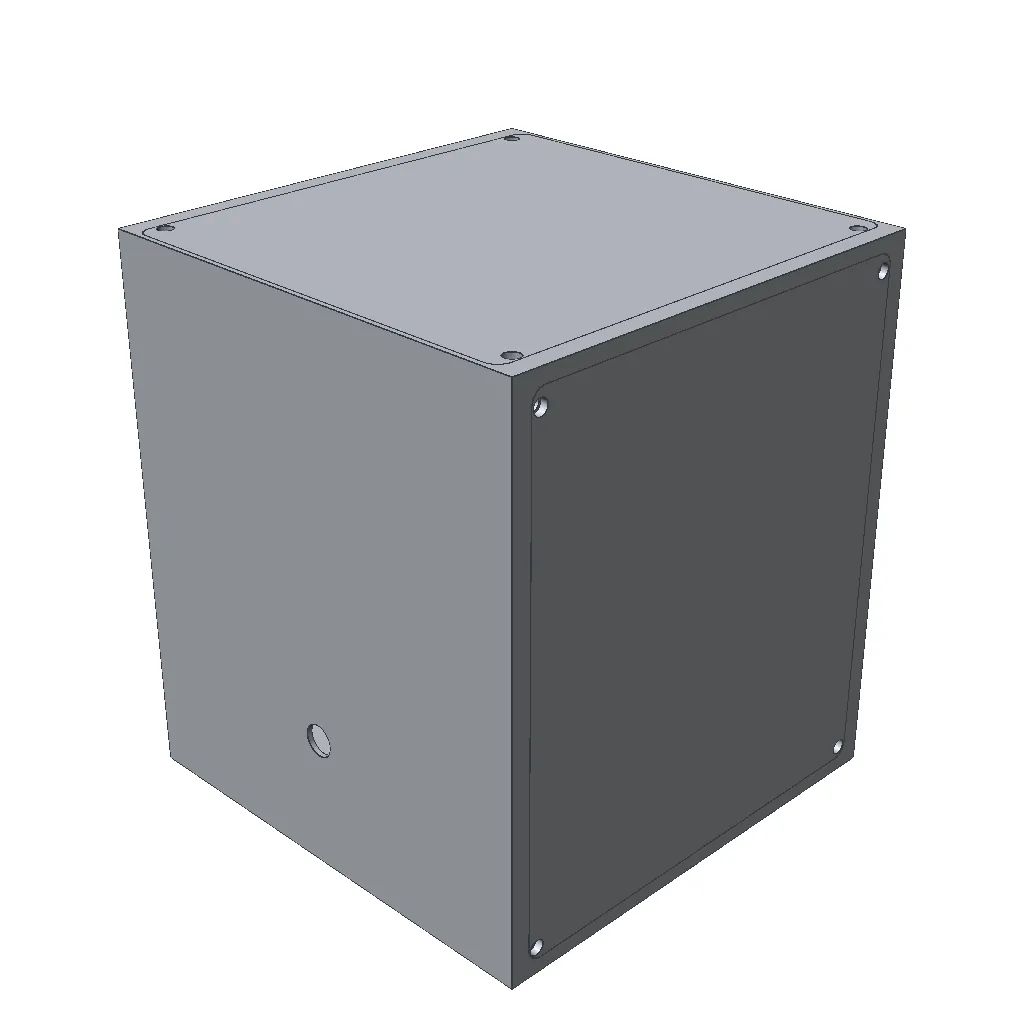
Machined aluminium
rail frame × 1 · side panel a × 2 · side panel b × 2 · top plate × 1 · bottom plate × 1
Engine output. Untextured CAD render.
-
4 · Check
9checks passed2checks failing0checks not measured
Measured
- Closed solids
- Overall size
- Cavity size
- Part fits with clearance
- Part inside the envelope
- Clear zone in front of a part
- Part can be removed
- Holes and bosses
- No two parts overlap
Still failing
- Board bay is smaller than specified
- Board clearance is under 0.5 mm
Counts cover checks that exist; the notes below list what has no check yet.
Failures go back to the design stage with the numbers; earlier failures stay on record.
-
5 · Scene
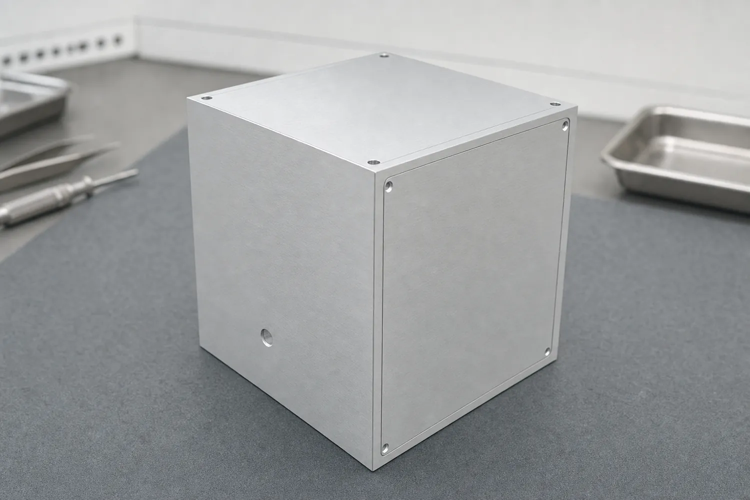
AI-generated from the CAD render above: same shape, only material, light and background added. Not to scale.
- Two checks still fail: the board bay is smaller than specified and the board clearance is under 0.5 mm. The brief card itself asked for a bay that does not fit inside the 100 mm envelope with the rails; that contradiction was found but not resolved.
- Rail width, the 6.5 mm protrusion limit and the 2.00 kg mass limit have no check yet, so they are not in the counts above: not passed, not failed, simply not measured.
- Side panels were made as separate bolted parts (the brief's open question).
Run on 2026-09-29 with our in-house engine as an internal test. Drawings and BOM for this case are not produced yet.