Inspection drone payload pod
Two hole patterns, one weight budget, and a camera that sees past the legs.
- Process
- Printed CF-nylon + CNC plate
- Quantity
- 20
- Region
- Global
- Environment
- Flight vibration
- Image
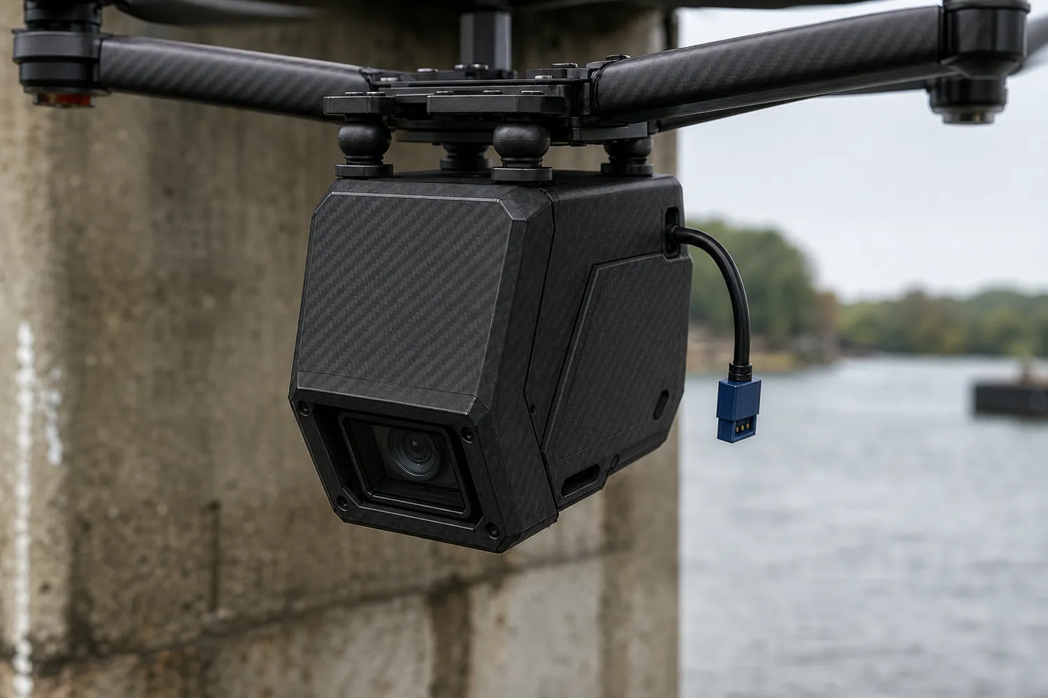
- Concept image, not to scale
Example brief · not client workWe wrote this brief ourselves; it is not client work. The design below was generated and checked by our engine as an internal test; read the notes under it before drawing conclusions.
The request, as a client would send it
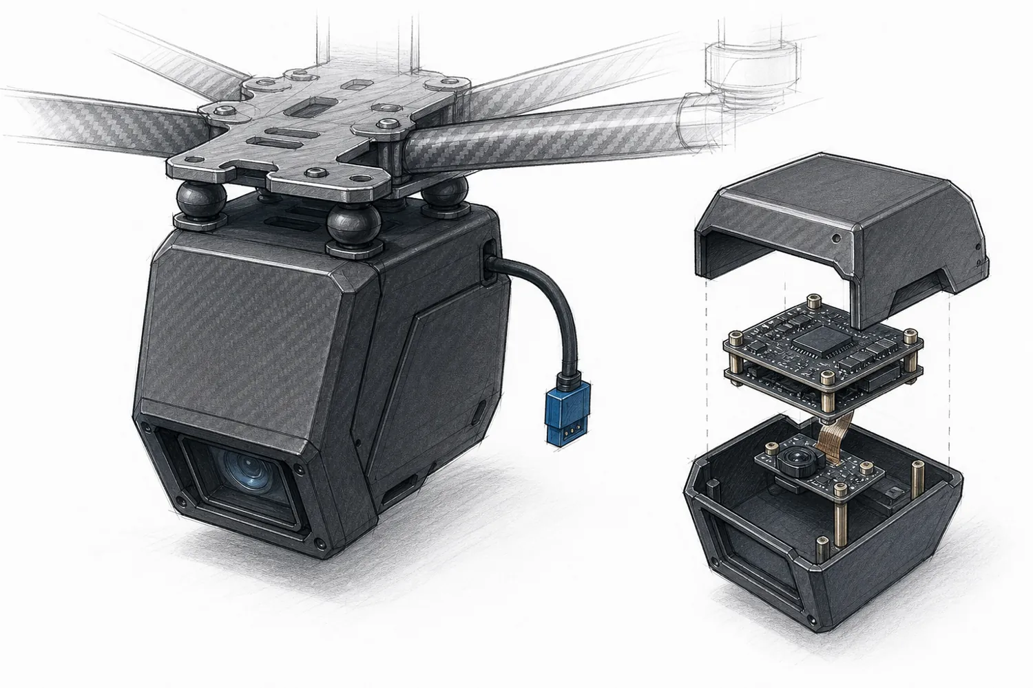
We inspect bridges and towers with our own quadcopter. We want a payload pod that hangs under the frame and carries our processing and camera: 20 units, printed in carbon-fiber nylon. - A flight/companion stack on the standard 30.5 x 30.5 mm M3 pattern (board 35 x 35 mm, like the Holybro Kakute H7 V2) - A Raspberry Pi HQ camera board, 38 x 38 mm, with M2.5 holes on a 30 x 30 mm pattern. Note that it's a different pattern from the stack. The lens points down and 30 degrees forward. - A 3S battery tap with an XT30 connector The pod hangs on four silicone damper balls (13 x 9 mm, 3.5 mm hole). When it shakes it must not hit the frame. The camera must see past the landing gear legs, which are 160 mm apart and 120 mm long. The whole pod must stay under 180 g including electronics; we estimate 70 g of parts. The top mounting plate can be a CNC aluminium plate. Our sketch is attached.
Attached by the client
Links in the request
- Holybro Kakute H7 V2 (opens in a new tab)35 x 35 mm, 30.5 x 30.5 mm M3
- Raspberry Pi HQ Camera product brief (opens in a new tab)38 x 38 mm, M2.5 on 30 x 30 mm
- Amass XT30U specification (opens in a new tab)about 10.2 x 5.2 x 13.7 mm
- Silicone damper balls (opens in a new tab)13 x 9 mm, 3.5 mm hole
- ArduPilot vibration damping guide (opens in a new tab)background
Product names are their owners' trademarks and are used only to describe size or parts.
Highlighted numbers came with the request; they are the values we would design to.
What we considered
| No. | Consideration | How it is checked |
|---|---|---|
| 01 | Two hole patterns in one pod The 30.5 mm M3 stack and the 30 mm M2.5 camera board each get their own standoffs; they are easy to mix up. | Hole positions and diameters for both patterns. |
| 02 | Room to shake Gaps around the pod so it can move on its dampers without touching the frame. | No collision between pod and frame; clear gap all round. |
| 03 | A camera view past the legs The camera window and its 30° tilt keep the landing gear out of the view. | Clear zone in front of the lens against the leg positions. |
| 04 | A weight budget with its working Estimated mass from volume and material density, plus the stated parts, against the 180 g limit. | Estimate and its inputs shown on the brief card. |
The question we would ask you
Fixed 30° camera tilt, or two positions?
A second position needs a pivot and a detent, adds weight, and changes the window shape.
What we do not claim
- Flight stability
- Damping performance
- Centre-of-mass analysis
From request to checked design
-
1 · Request
Two hole patterns, one weight budget, and a camera that sees past the legs.
Plain-language brief with 5 links and a sketch. Only the text goes into the pipeline.
-
2 · Brief card
3 parts to make4 parts to fit16 pass criteria
Assumed
- Quantity 20 as stated; prototype also FDM.
- Wall 2 mm nominal (not stated) — typical for PA-CF strength/mass balance.
- Component heights (stack 30 mm, camera 20 mm, XT30 16x11x8) estimated; XY from posting.
- and 2 more
Asked
- What is the damper mounting hole pattern on the airframe underside?
- How much vertical sway clearance exists between frame underside and pod top?
- and 1 more
-
3 · Design
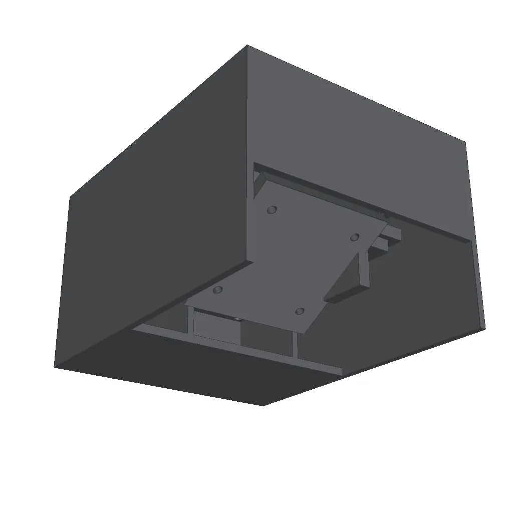
Printed CF-nylon, machined top plate
pod shell × 20 · top plate × 20 · camera cradle × 20
Engine output. Untextured CAD render.
-
4 · Check
17checks passed0checks failing4checks not measured
Measured
- Closed solids
- Overall size
- Part fits with clearance
- Cavity size
- Holes and bosses
- No two parts overlap
- Part inside the envelope
- Clear zone in front of a part
- Part can be removed
- Printing: overhangs
Counts cover checks that exist; the notes below list what has no check yet.
Failures go back to the design stage with the numbers; earlier failures stay on record.
-
5 · Scene
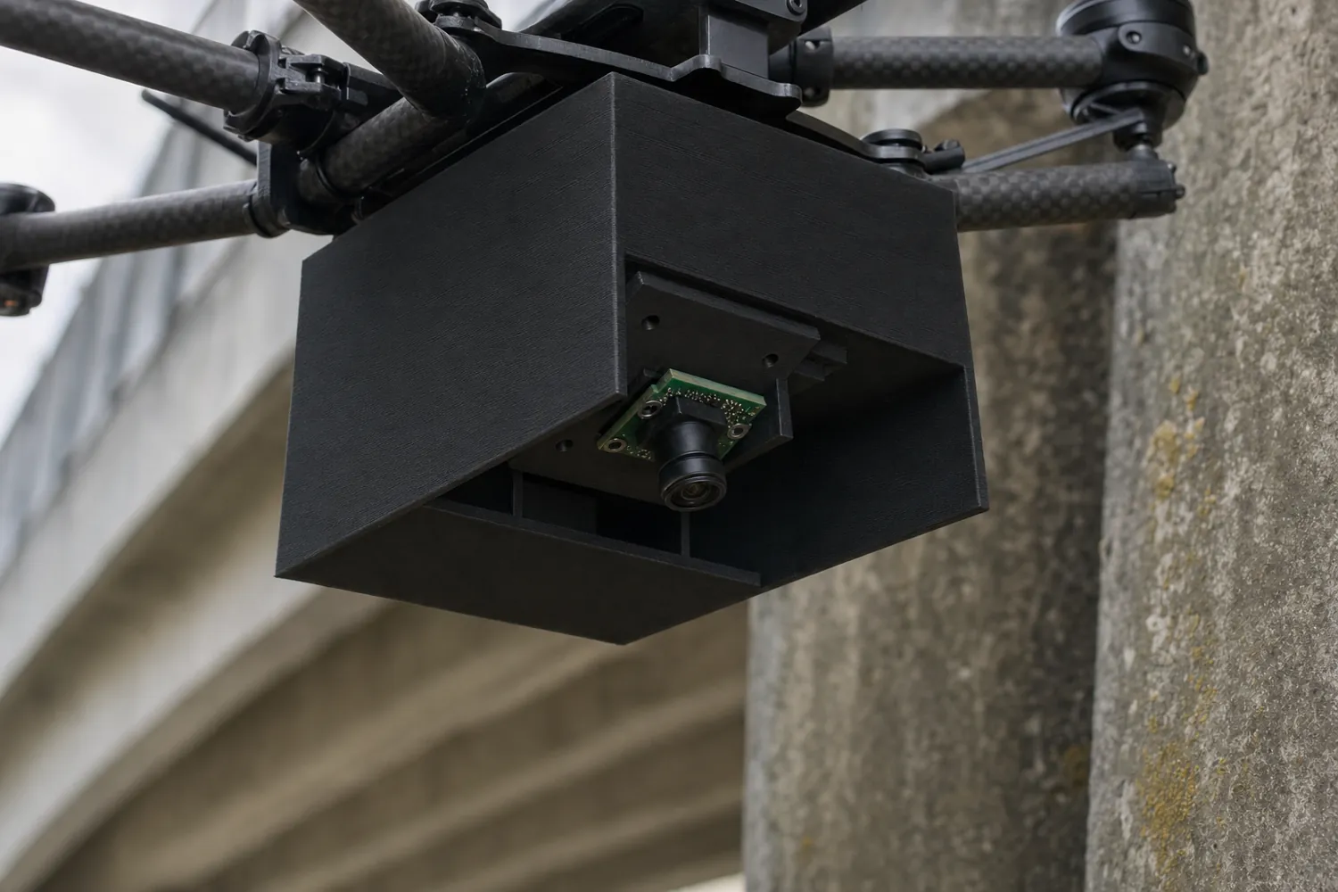
AI-generated from the CAD render above: same shape, only material, light and background added. Not to scale.
- The weight budget has no check yet, so it is not in the counts above. Our own estimate puts the pod near or over 180 g, mostly because of the aluminium top plate.
- The view past the landing gear and the shake gap to the frame have no check yet either: the airframe is not in the model.
- Four printing checks are not built yet and are counted as not measured.
Run on 2026-09-29 with our in-house engine as an internal test. Drawings and BOM for this case are not produced yet.