Cordless kettle power base
Mains and spills kept apart on a 120 V, 1500 W base.
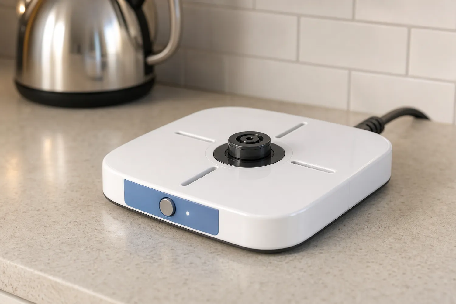
- Process
- Printed prototype → Injection
- Quantity
- 5,000
- Region
- US 120 V
- Environment
- Kitchen, spills
- Image
- Concept image, not to scale
Example brief · not client workWe wrote this brief ourselves; it is not client work. The 3D model, drawings and inspection results are in production and will replace the placeholders below.
The request, as a client would send it
We sell a 1.7 L stainless kettle in the US. Our supplier's power base cracks in shipping drop tests and scratches counters, so we want to design our own base and have a contract manufacturer make it. First order 5,000 units. Electrical: 120 V / 1500 W, so about 12.5 A through the connector. We will source a 360-degree cordless connector pair rated 120 V / 15 A (Strix-type; the base half is about 50 mm across, the supplier's drawing will follow). A small control PCB, 45 x 30 mm, with one push button and one status LED. A US cord set with strain relief, and a cord wrap underneath so the cord can be shortened on the counter. Please keep mains wiring and the low-voltage board clearly separated. Kettles get overfilled, so spilled water must drain away from anything electrical and never pool around the connector. Our kettle is similar in size and style to this one (not ours): the Nostalgia 1.7 L retro kettle. Our industrial designer's rough sketch of the base is attached. We will need UL 1082 for the kettle, so please design toward it and tell us where you are unsure. Rubber feet, white or matte grey, low profile.
Attached by the client
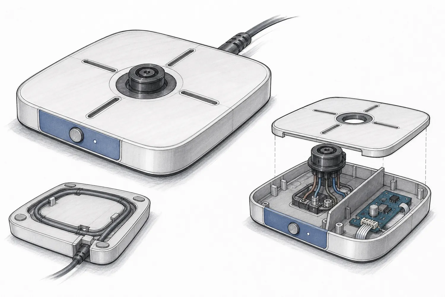
Links in the request
- Similar kettle (size and style reference) (opens in a new tab)1500 W, 360° base; not the client's product
- UL 1082 (household coffee makers and kettles) (opens in a new tab)US standard to design toward
- IEC 60335-2-15:2024 (opens in a new tab)EU/IEC equivalent, for a later market
Product names are their owners' trademarks and are used only to describe size or parts.
Highlighted numbers came with the request; they are the values we would design to.
What we considered
| No. | Consideration | How it is checked |
|---|---|---|
| 01 | Mains and low voltage in separate zones The connector wiring and the control board live on opposite sides of an internal barrier, with creepage and clearance distances listed. | Barrier present; distances between zones against the listed values. |
| 02 | Spills go around, not in Drain channels around the connector lead water to the outside edge, away from the electrical cavity. | Drain openings sit outside the sealed zone; no path from the top surface into it. |
| 03 | A cord that survives pulling Strain relief and cord wrap chosen from a parts catalogue so the quote includes them. | Parts in the BOM with their source. |
| 04 | Standards we don't have are named, not guessed Where the UL 1082 text isn't in our library, the report says "no source" for that clause. | Each standard-based rule carries its source or "no source". |
The question we would ask you
Detachable cord or fixed cord?
A detachable cord needs an appliance inlet and changes the barrier layout and the drop-test risk.
What we do not claim
- UL listing or any certification
- Heating or boiling performance
CAD, drawings and inspection
Model, drawings, parts list and inspection report
The 3D model, dimensioned drawings, parts list, and the first-try and final inspection results will appear here after the first build. First-try failures stay visible.